Deployment of the NM200E Core Verification System with Machine Learning and Artificial Intelligence
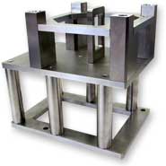
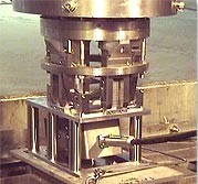
The Newton Labs approved method of deploying the NM200E system is to use a false fuel assembly. This unit is a rugged, protective carrier for the mapping head in the shape of a top nozzle that is designed to be picked up by the gripper on the refuel mast after the PWR refueling process is complete. This firm attachment and accurate positioning capability of the mast and bridge contribute to the precision of the fuel mapping process.
Overview of the Core Mapping Sequence
- The mapping head is mounted into its false fuel assembly and lowered onto a pull-pad in the cavity where it is picked up by the refuel mast gripper
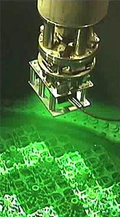
- Under the guidance of the NM200E operator, the bridge operator commands the bridge to a predefined location (i.e. fuel assembly N3) above the core. The refuel mast is set to maintain the mapping head at its operating height of five feet (1.5 m) above the core.
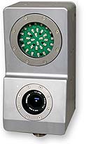
- The live video feed from the mapping head is displayed with a graphical alignment overlay generated from the fuel layout map. This reconfirms that the system is alive, ready and producing the anticipated images (clear, level, square, etc.)
- The NM200E operator indicates that the system can begin mapping into the user interface
- The NM200E takes a series of images at the first location that are processed using multiple techniques to accurately generate baffle and the position of each critical feature for all fuel assemblies in the field of view
- A global estimate of each critical feature’s location (in inches/mm) is generated, using the detected baffle position as a fixed reference point. The software identifies not only non-standard gaps, but also fuel assemblies that are rotated or shifted within the core.
- The core map updates automatically, saving all data to redundant storage devices
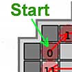
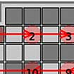
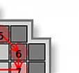
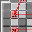
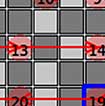
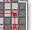
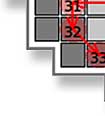
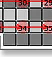
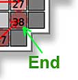
- The NM200E operator directs the bridge operator to the next predetermined mapping location, identified on the user interface (see figure below), maintaining a partially overlapping field of view (FOV). The procedure is repeated
- The software combines and correlates the s-hole locations identified in all previous FOVs with the current FOV to account for changes in rotation and alignment of the mapping head, refining the critical feature location estimates
- Upon reaching a baffle opposite the starting point, the mapping head is shifted laterally, maintaining some FOV overlap
- The process is repeated in the reverse direction, continuing in a zig-zag pattern until all fuel assemblies have been seen by the system
- The core map display on screen visually indicates the final results of each mapped fuel assembly in one of three colors:
- Green - for within tolerance
- Yellow - for within tolerance, but greater than the specified gap
- Red - for out-of-tolerance
 |
 |
 |
 |
 |
 |
 |
 |
 |
 |
 |
 |
 |
 |
 |
 |

