

High-Speed Precision Fiber Optic Coil Winding
Winding a thread of light in complex patterns at 300 rpm
The Challenge:
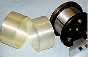
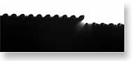
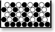
The challenge was to confirm and track each of six types of complex interleave patterns of machine-laid 130 micron fiber optic cable as it was being wound onto a 3 in. or 6 in. (76 mm or 152 mm) diameter mandrel rotating at 300 rpm.
The Solution:
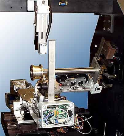
Newton engineers developed a machine vision system with a custom lens and illuminator mounted to a high-speed, three-axis motion stage. The camera and illuminator assembly maintained position above the fiber mandrel, providing a consistent field of view and focus of the fiber bundle. Determination of the position of the active strand was used within the Newton controller to identify the correct winding pattern for each stage of the fabrication. A typical coil may be 200 turns wide and 50 layers high.
What complicated the winding process was that the length of fiber to be wrapped was first wound onto two supply spools positioned on opposite sides of the mandrel. The mandrel winding starts at the middle of the length of fiber and fed from the supply spools. The interweave patterns to be tracked were formed by positioning the fiber coming from the A or B spools.